Antenna Analyzer Project
This antenna analyzer is based on the DDS module with built-in AD9851 chip (DDS: Direct digital synthesizer). There are a lot of similar analyzers already described (s. references below). I started to build the analyzer described by DG7EAO which worked well, but I found that the memory of the used microcontroller was pretty small in case I would like to add additional functionality in software. Nico (PA0NHC) presented an antenna analyzer which is not based on SWR bridge diodes but on the HF power detector chips AD8361ARTZ from Analog Devices, which promises a better linearity even for small hf voltages. The review of all the proposals of antenna analyzers lead to the following requirements:|
Requirements: - linear conversion from measured input voltages to digital values - frequency range from some 100 kHz to 30 MHz - use of a TFT touch display - large memory and high processing speed of the microcontroller - printed circuit board containing the display and BNC plug as well - interface to the PC software from K6BEZ to show the VSWR measures on the PC |
 |
Solution
To meet those requirements I bought the microcontroller Teensy 3.5, which is not that cheap (about 26 Euro in Germany) as the common Arduino controllers, but very fast and with a huge amount of memory. With a small addon it can be programmed like an Arduino using the Arduino development environment. The 2.8 inch touch TFT is from ebay (about 10 Euro) - take care to get one with the touch controller equipped.Specifications
| Board size | 116mm x 88mm |
| Antenna Connector | BNC |
| Frequency range | 0.1 - 30 MHz |
| Antenna Connector | BNC |
| Display | TFT touch 2.8" SPI |
| Power | 5V via microUSB (Teensy) |
Hardware
In the schematics below U1 measures the hf voltage provided by the DDS generator U3, while U2 measures the voltage, which results from the voltage devider R1/R2 and the antenna impedance on BNC plug J1. This left part of the schematics follows the proposal of PA0NHC. U1 and U2 convert the measured hf voltage into a DC voltage, which is led to the analog inputs 17 and 16 of the microcontroller U4. Some other outputs of the controller are used to drive the DDS and the TFT touch display.I have developed a double-sided PCB. All components with the exception of the display are soldered on the same side. The Teensy and the DDS are connected via female connectors to the board. The display is fixed by spacers and electrically connected via female connector.


Microcontroller software
Basic requirement is to have the Arduino software installed (Versions 1.0.6, 1.6.5-r5, 1.8.1, 1.8.2, 1.8.3 or 1.8.4). To compile Teensy related projects, you have to install the addon "Teensyduino" as well. See detailed information about the Teensy on the page of the PJRC site.Arduino software addon:
Teensyduino (software add-on for the Arduino software)
Required libraries:
Optimized ILI9341 TFT Library
Touchscreen Arduino Library for XPT2046 Touch Controller Chip
Source code of DL5DLA's antenna analyzer (ino file):
- will coming soon -
Usage
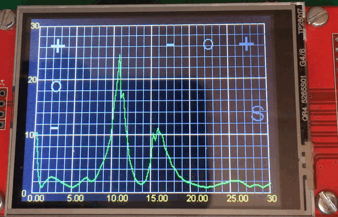
Currently the software is still in progress, but already working well (in my opinion ;-). After starting the module a welcome page is shown. Touching the display switches the display to the first of six pages:| Page 1: VSWR diagram Here the measured VSWR over the frequency is shown. The measurement is running continously and the screen is updated accordingly. On the left there are three softkeys: "+" (scale up the VSWR axis), "-" (scale down this axis) and "o" to do a auto-scale to best fitting the current measurement. On the top right part of the screen there are similar softkeys to scale the frequency axis resp. to show the complete frequency range ("o"). On the right side of the screen there is a further softkey "S" - press once to store the curent measurement and show it as additional red line on the screen. Press "S" again to remove it. I guess that this can be helpful to compare measurements. |
Click to enlarge and to navigate between pictures.
 |
Page 2: VSWR at center of ham bands Bar graph showing the current VSWR at the center of each ham band. Bar color changes according the measured VSWR values. |
 |
Page 3: Antenna impeance and VSWR Minimal and maximal values for each ham band. Since the calculation of these values takes some time, there is no continuous update of the page. |
 |
Page 4: Signal generator Enter the frequency to get a signal with constant frequency on the BNC output. |
 |
Page 5: PC interface Used to connect to the PC software of K6BEZ |
 |
Page 6: Calibration Plug in a reference resistor (e.g. 50 Ohm) and press "Calibration". The following measurement will be stored into EEPROM and used later for the real measurements |
 |
Stepping from page to page is done by a long press on the left or right side of the display (press until the page changes). Long press on the center of a page let the module jump to Page 1 (VSWR measurement).
The following video clip presents the use of the antenna analyzer. I connected some kind of a not adjusted HyEnd antenna just to get some different SWR values.
Calibration and reference measurements
Due to the decreasing hf voltage for increasing frequency and may me other issues (I have to think about ;-), there are some errors especially when measuring high VSWR values at frequencies beyond 10 MHz. For example, if a reference resistor of e.g. 500 Ohm is connected as a dummy antenna, one will not get a constant value of VSWR=500/50=10 for all frequencies, but increasing values above 10 for higher frequencies. My first idea was to find a formular which could be applied as a correction factor, but this only worked for smaller VSWR values and not at all for higher values. Finally I decided to apply a calibration function, which measures a reference resistor of e.g. 50 Ohm and stores the measured values (including the expected errors) in the EEPROM of the microcontroller. Later, for the real measurements of an antenna, the relative behavior of the stored reference values are used then to correct the measured values. This works pretty well for small VSWRs below VSWR=5. The following pictures show the VSWR for some reference resistors. The calibration was done with a reference of 50 Ohm.


Conclusion
Building this little antenna analyzer and programming the software for the microcontroller gave me a lot of fun. The microcontroller is fast enough and its memory big enough for further improvements and additions. The hardware could be improved by adding some kind of hf amplifier between DDS and antenna. Main problem is the reducing output voltage of the DDS for increasing frequencies, and probably the low input impedance (225 Ohm) of the hf detectors AD8361ARTZ.Peter Jonas (DL5DLA)
References
K6BEZ Antenna Analyzer from Beric Dunn (K6BEZ)Antennenanalysator from DG7EAO
pa0nhc SWRsweeper V2
Teensy USB Development Board